
|
|
Fiberglass and Composite Material Design Guide
The purpose of this design guide is to provide some general information on fiberglass and composite materials and to explain how to design products with these materials. If you have specific questions, please contact our engineers at Performance Composites and they will gladly assist you.
Composite Materials
Composites materials are made by combining two materials where one of the materials is a reinforcement (fiber) and the other material is a matrix (resin). The combination of the fiber and matrix provide characteristics superior to either of the materials utilized alone. Examples of composite products in nature are wood, bamboo and bone, and an example of an early man-made manufactured composite is mud and straw which has been used for over 10,000 years.
Composite materials are very versatile and are utilized in a variety of applications. Composite parts provide superior strength, stiffness and light weight, and can be formed into any shape. An ideal applications are large complex-shaped structures such as fiberglass covers. Composite products are ideal in applications where high-performance is required such as aerospace, race cars, boating, sporting goods, and industrial applications. The most widely used composite material is fiberglass in polyester resin, which is commonly referred to as fiberglass. Fiberglass is lightweight, corrosion resistant, economical, easily processed, has good mechanical properties, and has over 50 years of history. It is the dominant material in industries such as boat building and corrosion equipment, and it plays a major role in industries such as architecture, automotive, medical, recreational and industrial equipment.
The typical composite materials can be made with fibers such as fiberglass, carbon fiber (graphite), Kevlar, quartz and polyester. The fibers come in veil mat, short fibers mat, woven cloth, unidirectional tape, biaxial cloth or triaxial cloth. The resins are typically thermal set resins such as polyester, vinyl ester, epoxy, polyurethane and phenolic. The resins start as a liquid and polymerize during the cure process and harden. The weight ratio of fibers to resin can range from 20% fibers to 80% resin to 70% fibers to 30% resin. Typically the higher fiber content provides even better strength and stiffness, and continuous fibers provide better strength and stiffness. The use of composite materials provides engineers the ability to tailor the combination of fibers and resin to meet design requirement, and perform better than standard materials.
Composites materials are replacing metals and plastics in many industries and composites are the material of choice for many new applications. Please see table 1 for a comparison of cost and properties of commercial grade composite materials to aluminum, steel and wood.
TABLE 1
| Fiberglass & polyester | Graphite & epoxy | Wood (Douglas fir) | Aluminum Sheets 6061 T-6 | Steel Sheets | |
| Material Cost $/lb | $2.00-3.00 | $9.00-20.00+ | $0.80 | $4.50-10.00 | $.50-1.00 |
| Strength, yield (psi) | 30,000 | 60,000 | 2,400 | 35,000 | 60,000 |
| Stiffness (psi) | 1.2 x 10 6 | 8 x 10⁶ | 1.8 x 10⁶ | 10 x 106 | 30 x 106 |
| Density (lb/in3) | .055 | .065 | .02 | .10 | .30 |
Open Mold Manufacturing process
The most common manufacturing process for fiberglass is the wet lay-up or chopper gun spray process using an open mold. The shape of the part is determined by the shape of the mold, and the mold surface is typically in contact with the exterior of the part. Mold release is first applied to the mold to prevent the fiberglass part from adhering to the mold. Gel coat, which is pigmented resin, is applied to the mold to give the part color. Fiberglass and resin are then deposited onto the mold and the fiberglass is compressed by rollers, which evenly distributes the resin and removes air pockets. Multiple layers of fiberglass are deposited until the desired thickness is achieved. Once the resin is cured, the part is removed from the mold. Excess material is trimmed off, and the part is ready for paint and assembly. There are also closed mold processes for making fiberglass parts.

Vacuum Infusion Process (light RTM)
The Vacuum Infusion Process (VIP) is a technique that uses vacuum to pull resin into a laminate. The process is done first by loading the fabric fibers and core materials into the mold, then either using a vacuum bag or a counter mold to close the mold and create a vacuum seal. A vacuum pump is used to remove all of the air in the cavity and consolidate the fiber and core materials. Still under vacuum, resin is infused into the mold cavity to wet out the fiber. The locations of the vacuum ports and the resin insertion points need to be carefully planned to ensure full resin infusion. The advantage of the vacuum infusion process is to create a laminate with very high fiber content (up to 70% fibers by weight), thereby creating a very high strength and stiff part at minimum weight. Vacuum Infusion is also an efficient manufacturing process for complex laminate with many plies of fibers and core materials.
Prepreg manufacturing Process
Prepreg is fabric that has been pre-impregnated with resin (typically epoxy). The resin is cured to stage B, creating a gel that is neither liquid nor solid. Prepreg materials need to be kept frozen to prevent it from being fully cured. The prepreg is cut into shapes and applied to the mold in layers. A vacuum bag is then placed over the material and a vacuum pump draws all of the air out and compresses the layers together and consolidating the materials. The loaded mold is then put into an oven liquefying the resin so it will wet out the fibers. As the temperature increases, the resin will polymerizes and become hardens. The advantages of prepreg are very tight control of fibers ratio, low voids and precise location of the fabric and thickness uniformity. Prepreg materials are typically used for aerospace products and high-performance light weight parts.
Design Information
Like any material, fiberglass has advantages and disadvantages; however, in applications such as corrosion, low to medium volume production, very large parts, contoured or rounded parts and parts needing high specific strength, fiberglass is the material of choice. Fiberglass is a designer's ideal material, because the parts can be tailored to have strength and/or stiffness in the directions and locations that are necessary by strategically placing materials and orienting fiber direction. The design and manufacturing flexibility of fiberglass, provides opportunities to consolidate parts and to incorporate many features into the part to further reduce the total part price. Some general design guidelines are listed below:
| Material thickness | Typically range from 1/16" to 1/2". Can use sandwich construction to achieve lighter and stiffer parts. |
| Corner radius | Recommend 1/8" or larger |
| Shape | Will duplicate the shape of the mold. Can be heavily contoured. Undercuts can be accommodated using multi-piece molds. |
| Dimensional tolerance | Tool side can be + .010" of the tool Non Tool Side + .030" |
| Surface finish | Tool side can be class A Non tool side will be rough, but can be smoothed out Can be gel coated painted, or use any other |
| Shrinkage |
.002 in/in |
| Electrical properties | RF Transparent Excellent insulating characteristics Can provide EMI shielding through conductive coating |
| Fire retarding | Resins available in fire retardant applications meeting various ASTM or UL specifications |
| Corrosion | Resins available for corrosion applications, especially for hot brine, most acids, caustics, & chlorine gases |
Mechanics and analysis of composite materials
The mechanical properties of metal and plastics are isotropic (same strength and stiffness is all directions). The mechanical properties of composite materials are anisotropic (different strength and stiffness depending on the direction of fibers and loading). The difference between isotropic and anisotropic properties complicates the analysis of composite design, but most FEA programs have composite analysis capabilities. The anisotropic property of composite materials allows the engineer to tailor the composites materials to add strength and stiffness only in areas and directions where it is needed thereby reducing weight and costs. Our engineers are happy to help you with the analysis and design.
Tooling
Tooling or molds are used to define the shape of the fiberglass parts. The fiberglass part will pick up all shapes and features of the molds; therefore the quality of the part is heavily influenced by the quality of the mold. The molds can be either male or female. The female molds are the most common and they will produce a part with a smooth exterior surface while a male mold will produce a smooth interior surface (please see drawing below).


For very short production runs (less than 10 parts), temporary molds can be made from wood, foam, clay or plaster. These molds are economical and can be fabricated quickly, which will allow inexpensive prototype parts to be fabricated. For larger volume production, molds are typically made with fiberglass. These molds have a life expectancy of 10+ years and 1000+ cycles. Fiberglass molds are inexpensive and usually only cost 6 to 10 times the price of the part.
The mold is a mirror image of the part. To create a mold, a master (plug) is required. The master can be an actual part, or can be fabricated out of wood, foam, plaster, or clay. The exact shape and finish of the master will be transferred to the mold. Once the master is completed, it is polished, waxed and the mold is built up on the master. The fabrication technique of the mold is similar to fabricating a fiberglass part except that tooling materials (gel coat, resins, and cloth) are used to provide a durable mold that has low shrinkage and good dimensional stability. Once the mold is laminated, it is reinforced with wood, fiberglass or a metal structure to ensure that it retains the proper shape. The mold is then removed from the master and put into production.
Design covers and enclosures with Fiberglass and Composites
Fiberglass and composites are ideal material for making shaped shell structures. It is the dominant material in applications such as boat hulls, small aircraft, architectural domes, and camper shells. Composites are also an ideal material for making covers and enclosures for machinery and equipment. The covers can have any shape or contour the designer wishes. They are lightweight, corrosion resistant, have class A finish, and are cost effective.
The cover can also be large and complex so one single cover can replace numerous individual panels. Consolidating parts greatly reduces costs and simplifies assembly. Traditionally, covers and enclosure for machinery and equipment have been made out of sheet metal. It is a material many engineers and designers are familiar with, and sheet metal is a good choice for covers that are simple and box shaped. If the covers need to have contour, such as a chamfer or radius corners, or if the covers are large, fiberglass and composites are the materials of choice.
The cover of the machine conveys a very strong signal to the customer as to the quality and performance of the machine. A Corvette would not be a world-class sports car if it had a boxy sheet metal body.
Performance Composites has helped numerous companies design, develop and manufacture state of the art covers and enclosures. The stylish covers have helped our customers differentiate their products and have helped them increase their sales and market share. We can do the same for you. If you have any questions or specific applications, please contact us via e-mail or phone.
Advantages and disadvantages of fiberglass and sheet metal enclosures
|
Fiberglass or Composite Material |
Sheet Metal |
|
|
Production quantities |
* 10 to 1000+ per year. |
* 1 to 1000+ per year. |
| Size |
* Can be made in any size (limited by shipping constraints). * Larger parts are more cost effective. |
* Difficult to make covers larger than 3’ x 5’ x 3’ due to weight and handling issues. |
|
Shape |
* Can have any shape the designers desire. Able to make your part unique. * Shape can also be used to stiffen the part (i.e. molded in ribs). |
* Limited to simple box shapes. * Complex shapes can be made but will be expensive. |
|
Cost
|
* For complex shapes or large covers, fiberglass will be the most economical. * For simple small box shapes sheet metal will be cheaper. |
* Economical for simple box shapes. * Become expensive if the shape is complex or if the cover is large. * If aluminum is used to save weight or stainless steel is used for corrosion resistant, the covers will cost more than fiberglass. |
|
Exterior finish
|
* Can be painted or gel coated Class A finish * The finish can be either textured or glossy. |
* Can be painted (textured or glossy) or powder coated. * Difficult to achieve good smooth aesthetic appearance. |
|
Tooling
|
* Requires mold and fixtures to fabricate the part. * Typical cost of tooling is 6 to 10 times the part price. * Tools can be made within 4 weeks. |
* Need some jigs and fixtures. |
|
Durability
|
* Will not dent or bend, but will crack when damaged. * Cracks can be repaired. |
* Will dent and bend when damaged. |
|
Corrosion Resistant
|
* Will not corrode. * Can tolerate most chemicals, solvents, acids, and bases. |
* Will corrode if the metal is exposed to moisture or chemicals. |
|
Fire resistance
|
* Fire retardant resins can be used if required. Certified for use on interior of buildings, buses, and aircrafts. |
* Will not burn. |
|
EMI/ RFI shielding, and electro static grounding |
* Can add a conductive layer to provide EMI/RFI shielding and electro static grounding. |
* The cover is conductive and will block EMI/RFI. |
|
Stiffness
|
* Covers can be made very stiff. * If a large unsupported span is necessary honeycomb core can be used to increase stiffness. |
* Very flexible. * Need to add stiffeners of additional structure for large covers, which often warp and distort the surface. |
|
Tolerances
|
* + .010 on mold side and + .030 on non-tool mold for critical features. * Overall size and shape + .060 on large covers. |
* + .010 on critical features. Overall size and shape + .060 on large covers. |
|
Weight
|
* Density of the material is .05 lb/ft^3. * Typically fiberglass covers will weigh less than ½ of steel covers (typical wall thickness is 1/8” to ¼”). * Lighter covers are often safer. |
* Density of the material is .3 lb/ft^3. * Larger covers get very heavy due to the additional reinforcement necessary. |
Carbon Fiber Composite Design Guide
The purpose of this design guide is to provide general information and specifications on graphite (carbon fiber) composite materials and some guidelines for designing lightweight high performance products with graphite composites. If you have more specific questions, please contact our engineers at Performance Composites, and they will gladly assist you.
Graphite composites have exceptional mechanical properties which are unequalled by other materials. The material is strong, stiff, and lightweight. Graphite composite is the material of choice for applications where lightweight & superior performance is paramount, such as components for spacecrafts, fighter aircrafts, and race cars.
Composite materials are made by combining reinforcement (fiber) with matrix (resin), and this combination of the fiber and matrix provide characteristics superior to either of the materials alone. In a composite material, the fiber carry majority of the load, and is the major contributor in the material properties. The resin helps to transfer load between fibers, prevents the fibers from buckling, and binds the materials together.
Graphite fibers (sometimes called carbon fibers) are made from organic polymer such as polyacrylonitrile. The material is drawn into fibers and kept under tension while it is heated under high temperature (> 1000C). 2 dimensional carbon-carbon crystals (graphite) are formed when the hydrogen is driven out. The carbon-carbon chain has extremely strong molecular bonds (diamond is a 3 dimensional carbon-carbon crystal), and that is what gives the fibers its superior mechanical properties.
Historically, graphite composites have been very expensive, which limited its use to only special applications. However, over the past fifteen years, as the volume of graphite fiber consumption has increased and the manufacturing processes have improved, the price of graphite composites has steadily declined. Today graphite composites are economically viable in many applications such as sporting goods, performance boats, performance vehicles, and high performance industrial machinery.
Applications of Graphite Composite Materials
Composite materials are extremely versatile. The engineer can choose from a wide variety of fibers and resins to obtain the desired material properties. Also the material thickness and fiber orientations can be optimized for each application.
The advantages of graphite composites are:
1. High specific stiffness (stiffness divided by density)
2. High specific strength (strength divided by density)
3. Extremely low coefficient of thermal expansion (CTE)
4. X-ray transparent (due to its low molecular weight)
Please see table 1 for a comparison of costs and mechanical properties of graphite composite, fiberglass composite, aluminum, and steel. Due to the wide variety of graphite fibers and resins available, and the numerous combinations of the materials, the properties are listed in ranges.
TABLE 1
|
Graphite Composite (aerospace grade) |
Graphite Composite (commercial grade) |
Fiberglass Composite |
Aluminum 6061 T-6 |
Steel, Mild |
|
|
Cost $/LB |
$20-$250+ |
$5-$20 |
$1.50-$3.00 |
$3 |
$.30 |
|
Strength (psi) |
90,000–200,000 |
50,000–90,000 |
20,000-35,000 |
35,000 |
60,000 |
|
Stiffness (psi) |
10 x 106 - 50 x 106 |
8 x 10⁶ - 10 x 106 |
1 x 10⁶ - 1.5 x 10⁶ |
10 x 106 |
30 x 106 |
|
Density (lb/in3) |
.050 |
.050 |
.055 |
.10 |
.30 |
|
Specific Strength |
1.8 x 10⁶ - 4 x 10⁶ |
1 x 10⁶ - 1.8 x 10⁶ |
363,640-636,360 |
350,000 |
200,000 |
|
Specific Stiffness |
200 x 106-1,000 x 106 |
160 x 106-200 x 106 |
18 x 106-27 x 106 |
100 x 106 |
100 x 106 |
|
CTE (in/in-F) |
-1 x 10⁻⁶ – 1 x 10⁻⁶ |
1 x 10⁻⁶ – 2 x 10⁻⁶ |
6 x 10⁻⁶ – 8 x 10⁻⁶ |
13 x 10-6 |
7 x 10⁻⁶ |
Applications for High Specific Stiffness
Graphite composites are ideally suited for applications where high stiffness and low weight is required. Most metals used for structural applications have very similar specific stiffness, which is around 100 x 10^6 psi. If an application demands high stiffness and lightweight, graphite composites are the only material of choice.
Examples are:
- Spacecraft structure
- Aircraft structure
- Drive shaft for trucks and high performance vehicles
- Machinery rollers
- Sail boat mast and boom
- Bicycle frame
- Machinery components that experience high acceleration & require stiffness & precision
Applications for High Specific Strengths
Graphite composites are widely used for lightweight structures that need to carry extremely high loads.
Examples are:
- Motorcycle components (skid plates, rock guards)
- Fishing pole
- Golf club shaft
- Aircraft structure
- Satellite antenna structures
- Racecar chassis
Applications for Low CTE
Graphite fiber has a negative coefficient of thermal expansion, which means when it is heated it will shrink. When the graphite fibers are put into a resin matrix (positive CTE), the composite can be tailored to have almost zero CTE. Graphite composites are used for high precision and thermally stable applications.
Examples are:
- High precision antennas
- Scanning & imaging machines
- Precision optical devices
- Metrology equipment
Manufacturing Process
Graphite composite components are manufactured utilizing a molding process. The graphite fibers can be woven into cloth, braided into tubes, or made into unidirectional tapes. The fibers are next coated with resin. This fiber & resin mix can be partially cured then frozen to create a pre-preg, or the fiber & resin mix can be used wet. The graphite fiber & resin mix is then placed into a mold in layers. The number of layers and the orientation of the layers will depend on the mechanical properties desired. The layers of graphite is then compacted and consolidated in the mold by pressure from a press or from a vacuum bag. Depending on the resin system, the part can be cured at room temperature or elevated temperature. Once the part is cured, the part is removed from the mold, and it is ready for finishing operations such as trimming and drilling.
Design Information
Graphite composites are considered designer's material, because the parts can be tailored to have strength and or stiffness in the directions and locations that are necessary by strategically placing materials and orienting fiber direction. Also the design and manufacturing flexibility that graphite composites offers provide opportunities to consolidate parts and to incorporate many features into the part to further reduce the total part price. Some general design guidelines are listed below:
|
Material Thickness |
Typically range from .040” to ½”. Can use sandwich construction to achieve lighter and stiffer parts. |
|
Corner Radius |
Recommend 1/8” or larger |
|
Shape |
Will duplicate the shape of the mold. Can be heavily contoured. |
|
Dimensional Tolerance |
+.010” |
|
Surface Finish |
Tool side can be class A Can be gel coated painted, or use any other surface coating |
|
Shrinkage |
.0005 in/in |
|
Electrical Properties |
Electrical conductive |
|
Fire Retarding |
Resins available in fire retardant applications meeting various ASTM classes & smoke generation requirements |
|
Corrosion |
Resins available for corrosion applications, especially for hot brine, most acids, caustics, & chlorine gases |
Tooling
Molds are used to define the shape of the composite parts. The graphite composite part will pick up all shapes and features of the molds; therefore the quality of the part is heavily influenced by the quality of the mold. The molds can be either male or female. The female molds are the most common and they will produce a part with a smooth exterior surface while a male mold will produce a smooth interior surface. A matched mold (male and female) is required if the part is consolidated using a press. The molds can be made with composite materials, metal filled epoxy, or machined from aluminum or steel. The type of mold and materials used depends on the type of part and the production quantity.
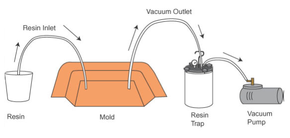
Vacuum Infusion Process (VIP) Guide
The Vacuum Infusion Process (VIP) is a cost effective process for making high quality composite parts. Advantages of VIP include higher quality, better consistency, higher glass content (higher specific strength and stiffness), good interior finish, faster cycle time and lower cost.
The Vacuum Infusion Process (VIP) utilizes vacuum to infuse resin into the laminate. The first step is to load the fabric fibers and core materials into the mold. Also ribs, inserts and any other components can be added, and this is done without resin. Next the dry material is seal closed using a vacuum bag or a counter mold. High vacuum pump (25 in Hg or more) is used to remove all of the air in the cavity and consolidate the fiber and core materials. Still under vacuum, resin is infused into the mold cavity to wet out the fabric fibers and core. The vacuum infusion process is very simple in concept; however, it requires detail planning and process design so the parts can be infused in a reasonable amount of time without any dry spots. The rate of infusion depends on the viscosity of the resin, the distance the resin has to flow, the permeability of the media, and the amount of vacuum. Therefore, the choice of materials, flow media, resin flow layout, and location of vacuum ports are critical in making good parts. The advantage of the vacuum infusion process is to create a laminate with very high fiber content (up to 70% fibers by weight), thereby creating a very high strength and stiff part at minimum weight. Vacuum Infusion is also an efficient manufacturing process for complex laminate with many plies of fibers and core materials.
Benefits of VIP:
- Higher fiber-to-resin ratio (up to 70% fibers by weight)
- Higher strength and stiffness
- No resin entrapped air/ very low voids
- Very consistent laminate with great process control (less human errors)
- Minimal part shrinkage with good surface profile and accuracy
- Can have good outside and inside surfaces
- Efficient to laminate complex fiber layers, ribs, inserts and cores
- Cleaner process with no VOC air pollution
- Faster cycle time
Short coming of VIP:
- Complicated set-up and need to develop the optimal vacuum ports and resin injection locations
- If there is a vacuum leak, the part can be scrapped
- Cosmetic finish on the surface is not as good as open mold process due to fabric print through; however, a barrier coat can be used to improve the finish.
- Tooling cost is higher
- VIP materials cost more than standard resins and fabric
- Will consume some disposable supplies
VIP Set-up and Equipment
Below is the typical VIP setup.
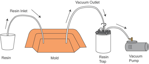
Typically vacuum ports or channels are created around the perimeter of the part and the resin insertion is at the center of the part. The goal is to have the resin wet out the entire part as quickly as possible without any dry areas. For large or complex parts, additional resin inlet lines can be added.
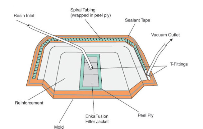
A good quality mold is required for vacuum infusion. It needs to be vacuum tight and can sustain the high exothermic temperatures from the part curing.
Select your fiber reinforcement, core and resin
Choosing the correct fiber reinforcement, resin and core materials are important decisions for VIP. Any types of fibers can be used, but the proper fiber size, the type of weave and style will allow for VIP. The resin used for VIP need to have low viscosity (ideally less than 400 centipoise) to ensure the infusion can be completed prior to the resin cure. There are numerous polyester, vinyl ester and epoxy resins formulated for VIP. For sandwich construction utilizing a core (such as balsa or foam), resin grooves can be added to the core to improve the resin flow. Flow media, which is a plastic mesh, can be added to the laminate to improve the resin flow and speed up the infusion process. The flow media is removed after the part is demolded. The engineers at Performance Composites can help you choose the correct materials and develop a VIP process that will meet your criteria and cost target.